
I’ve been dying to get a planer for a while now, and recently was lucky enough to acquire this one off Craigslist. It needed a little work to get going though.
The main problem was that it was jammed so that turning the hand crank with any reasonable amount of force wouldn’t actually raise or lower the cutting head. It looked like the main culprit was a damaged chain tensioner. The chain drives a nut on a screw post in each of the four corners of the machine to raise and lower the cutting head. When the chain isn’t well-tensioned, it doesn’t pull evenly on all four nuts, which means some of them (especially the one closest to the hand crank) can move more than the others, resulting in the whole assembly tilting. Everything is pretty stiff, so just a little tilting causes a lot of jamming.

In order to access the all the sprockets you have to remove quite a few pieces, ideally in a somewhat particular order. I found this great write up by Lew Plauny on how to do this (text also copied below just in case that link ever gets lost): http://lumberjocks.com/topics/25101
I would recommend anyone doing this to place the planer on a workbench so the planer can be rotated and tilted to access fasteners and to have a strong light source on the work space. One will be removing a number of screws and bolts so I recommend replacing the screws and bolts into their holes after planer parts are removed. I found having a complete set of regular and metric T shaped Allen wrenches and good set of Philips head screwdrivers helpful. I would also recommend reading all of the below before starting to disassemble the DW735.
1. Remove the yellow plastic top cover by removing the 4 hex bolts with the DeWalt 5/32 Allen wrench and set aside, replace hex bolts in the holes. Note that when this top is installed it presses down and activates an cross shaped safety switch on the top right of the cutter/roller assembly. When the top is off, the On/Off switch will not work. If you later wish to test the planer with the top off ( be careful if the cutters are exposed ), you must depress this chrome colored switch with a piece of wood or a tool.
2. The Power Switch and Circuit Breaker mountings on the front of the planer do not have to be removed in order to remove the yellow plastic “Cover Assembly”. They also do not have to be removed to loosen the front panel.
3. I removed both the left and right black side covers from the “Cover Assembly” which makes the “Cover Assembly” removal easier, exposed the interior gears for inspection. No work needed done on the side assemblies.
4. If you are wondering the “Cover Assembly”, Part No. 5140010-75, is the yellow plastic cover you need to remove to clear the jam and adjust the post travel. Not obvious when just looking at the machine is the “Cover Assembly” is a molded continuous 4 sided plastic that you have to loosen and lift up over the 4 chrome posts to remove.
5. The large black carry handles (the DW735 is almost too heavy to be called portable) have to be removed with a #6 metric Allen wrench because the inside notches in the handle extend over the edge of the yellow plastic side assembly.
6. There are 3 Philips screws that need to be removed at the top of the front panel to loosen the front panel.
7. The Material Removal Scale hides a Philips screw in the center of the cover front which has to be removed to loosen the front panel bottom. There are two small flat head 7/64 or #3 metric hex bolts left and right on the front panel that also need removed. Replace all in their holes.
8. There are 2 Philips screws at the back of the yellow cover that need to be removed.
9. The 2 speed Speed Lever Control must be removed with a 5/32 Allen wrench.
10. The crank wheel needs to be removed with a 5/32 Allen wrench.
11. In order to have enough wiring loose to lift the “Cover Assembly” over the 4 chrome screw posts, you will need to unscrew the 2 Philips screws holding the 2 green ground wires to the base. There is a black screw with a small black lock washer between the wire connector and the black base. The lock washers are hard to see (black on black on black) so don’t lose them. Replace screws.
12. In order to raise the “Cover Assembly” over the chrome posts and set it aside you will also have to remove 2 Philips screws from a black bracket holding the power wires to the right side of the base assembly. I did not have to remove any of the switch snap on wiring connectors in order to lift the “Cover Assembly” over the chrome posts and I could set the cover far enough aside to work on the post assemblies.
13. The front panel cover has to be removed because it hides 2 long 5/32 hex bolts that hold the “Cover Assembly” to the cutter/roller assembly base. There are 2 Philips screws that need to be removed at the back of the “Cover Assembly”.
14. The depth gauge on the front right chrome post also needs to be removed to remove the “Cover Assembly”. Top of chrome post is 5/32 Allen and bottom is 2 Philips screws.
15. The back side of the “Cover Assembly” can be pressed out and lifted up over the dust chute but;
16. With the “Cover Assembly” set aside, I could not move the jammed sprockets, drive chain or twist the chrome posts by hand. To test further I had to remove the chain drive that circumvents the 4 chrome post sprockets. To do this, loosen the 2 Philips screws that hold the chain tension bracket. Be careful to use a tight fitting Philips screw driver. I had to put down pressure on the screw driver and add torque to the screw driver with an open ended wrench on the screw driver shaft. The screws were really tight.
17. I completely removed the chain and thoroughly cleaned the sprockets, chain and posts.
18. Eureka. With the chain removed I could easily turn the sprockets with channel locks. Although I moved the sprockets to test them, I did not move them far and I made sure I returned them to their original position. I tried to hand twist the 4 chrome posts. 3 were tight. The cause of my jam was a loose left front chrome post turning until it jammed my other 3 sprocket posts.
19. I tightened the loose post by sliding that corner of the planer off the edge of my workbench. The bottom of the chrome post has a detent for an open end wrench to fit onto and the hex bolt head underneath the planer cast base is a #6 metric Allen head. If I had been smarter, I could have tested for this hex bolt looseness from underneath before disassembly but I would have had to disassemble to fix the jam anyway.
20. I tightened the loose post (and checked the other 3). As the post spirals looked symmetric, I assumed it did not matter what position the post was in when tightened.
21. With the chain off, the sprocket assemblies move easily with a channel lock pliers. I did not move the 3 tight posts’ sprockets but moved the loose post’s sprocket height to match the sprocket height of the other three. I measured carefully from both the bottom and the top of the other 3 posts.
22. I replaced the chain, the chain tension bracket and fitted the hand wheel. The cutter assembly moved smoothly to the top. Actually smoother than it moved when the planer was new. I re-cleaned the posts and WD40’d the parts.
23. With the jam fixed I reversed the sequence of operations above.
24. If you need to disassemble the minimum depth stop knob control, note that inside the plastic knob that you spin for min depth there is hex set screw that holds in a small spring and a detent ball bearing. Remove the hex set screw, spring and ball bearing with a magnet before removing the hex bolt holding the control wheel on. Otherwise the ball bearing finds the floor quickly.
25. Note that when the
26. If you decide to change planer knife edges (knives have two reversible sharpened edges) use the magnets on the DeWalt hex wrench to lift the knife clamp and to lift and reverse the knife edge. I did use a longer stronger T handle hex wrench to remove and replace the hex head screws as they were really in tight. Those magnets on the DeWalt hex wrench handle are a great finger saving idea. Push down on the knife roller lock on the left side of the roller to unlock and roll the knife roller with a piece of wood. The Operating Manual instructions and hints work good doing this.— Lew Plauny @ Montrose PA
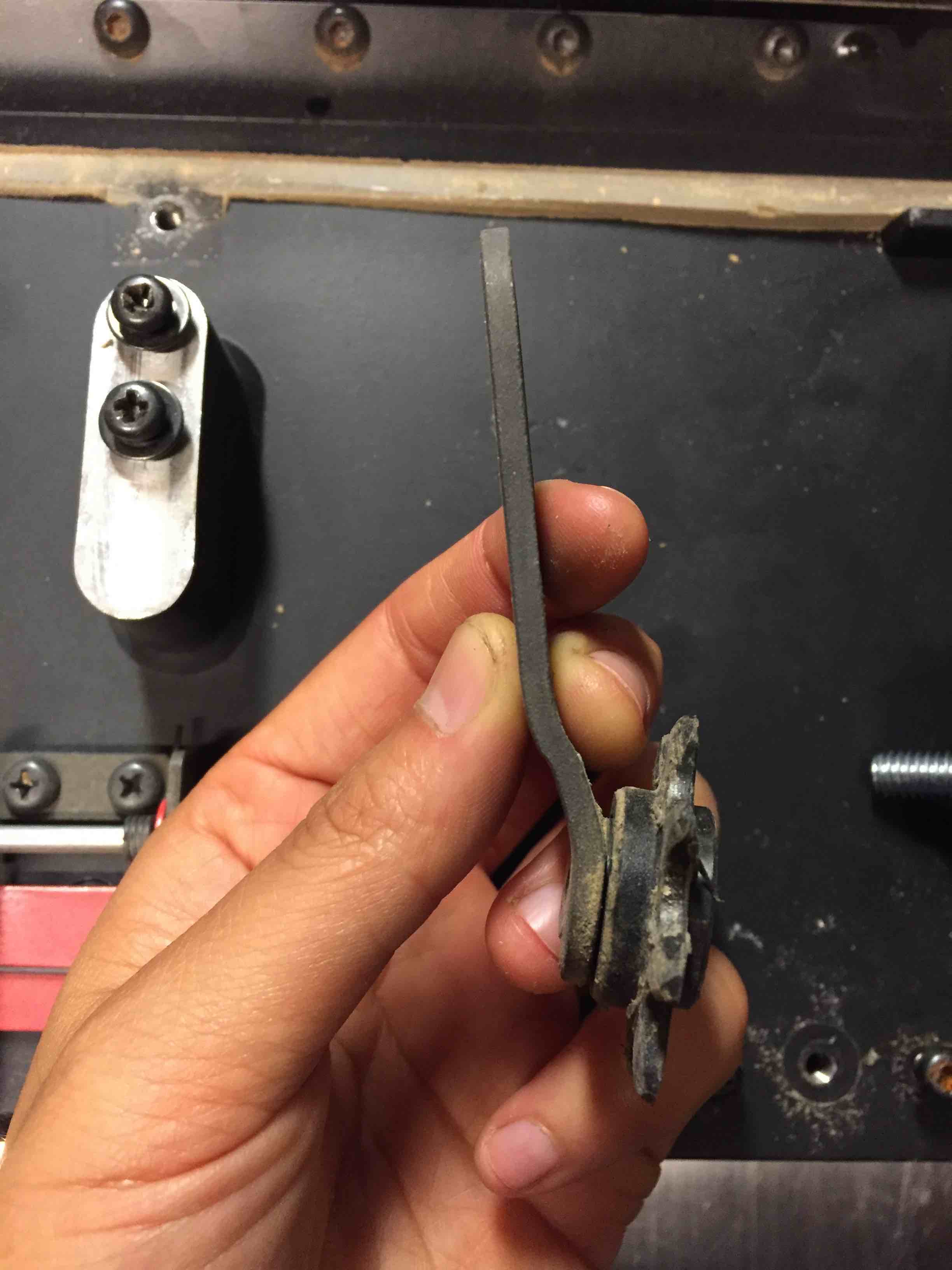
I thought it would be easiest to machine a thick bracket out of aluminum, rather than weld/bend something from steel. Thankfully, the chain is also standard bike chain pitch, so it was easy to find a replacement sprocket from a bike derailleur.


With the chain still slack, I leveled the cutting head by turning each sprocket individually until they were all the same height off the base (I just used a chunk of scrap metal as a height gauge). Luckily, the platform seemed to be fairly well-leveled out of the factory because after I leveled it again, the chain slipped on without too much extra fiddling with how much the sprockets were turned.
Next, I turned my attention to cleaning and lubing the screw posts. What’s worked well for me before on various woodworking tools is finishing paste wax (if there are other suggestions, I’d love to hear them!). I just applied it with an old toothbrush (don’t throw those out, they’re so useful!). I also made sure to rub a thin coat on the table to help wood slide better on it.

Cranking the assembly up and down a few times produced this lovely residue, which I cleaned off. The theory is that the wax helps collect some of the extra particles into chunks that are easy for me to remove. And it leaves a thin coat of dry wax behind. As long as I keep the chain tensioned and the screws clean, I feel like this assembly should be good to go for a good while.

Finally, time to fire it all up and see how it cuts. I’ve had this fork section of a tree sitting around for a while, so I chainsawed a slab.

After numerous passes at 1/16″, this planer produced a flat board. I am happy.

Leave a Reply
You must be logged in to post a comment.