
As I mentioned in the last post, my next step on this project was to lift the frame up higher so I could fit a lot more stuff underneath. The original frame is made from thin-walled 2″ square tubing, so I decided to also go with 0.063″ wall 2″ square tubing.

I borrowed time on a sweet welding table at another shop.


The original frame has casters, but also threaded feet that you can screw down when you don’t want the laser to roll around anymore. I duplicated that feature by welding some stainless steel nuts to some square plates that are welded to the ends of the tubes on the bottom. Its cool that you can weld stainless to mild, and super convenient, too, since stainless nuts don’t come with zinc coatings (inhaling zinc is bad).

Despite no 45 degree bracing for the legs, the frame felt plenty stiff at this point. 2″ tube is pretty big, and its really just not that tall. But considering I was going to just throw some wood down as a shelf, I thought an additional center brace would be nice. The fume extractor and the chiller, which will both go here, are both pretty heavy.


I brought it home to do a quick test fit against the existing legs. Some of them were a bit off, I took a closer look and I think one of the leg tubes was misaligned when I welded it, oops. Good thing I didn’t make it any stiffer than it is. I was pretty confident that I would be able to smush everything in place with some clamps.

This next part is also directly mimicking the original frame. 0.063″ is too thin to thread for the M7 bolts that hold the casters in. So like the original frame, I welded on a piece of 1/8″ and threaded that. All the plates were pre-drilled to the tap diameter, then I welded them in place, drilled through the tube wall at the tap diameter, and threaded both layers together.


I wiped down the whole frame with IPA and then did a bunch of painting, both of the frame and of my driveway…

I had just enough left over pieces of melamine to cover the shelf! The shelf is made of two separate pieces that meet over the center support and lock each other in with the leg cutouts.


Now for mounting the actual laser tube: the laser came with the holder on the left with 3 nylon screws to adjust the position of the tube – sounds like a pain. The one on the right seems like a pretty popular replacement for the one on the left, since it is much easier to adjust (mounting holes are slotted, and there is a knob attached to a pinion gear that moves the tube clamp up and down, poorly shown in this photo). It would have been nice to use it directly, however, it is too wide and interferes with the rod that couples both belts for moving the Y axis.
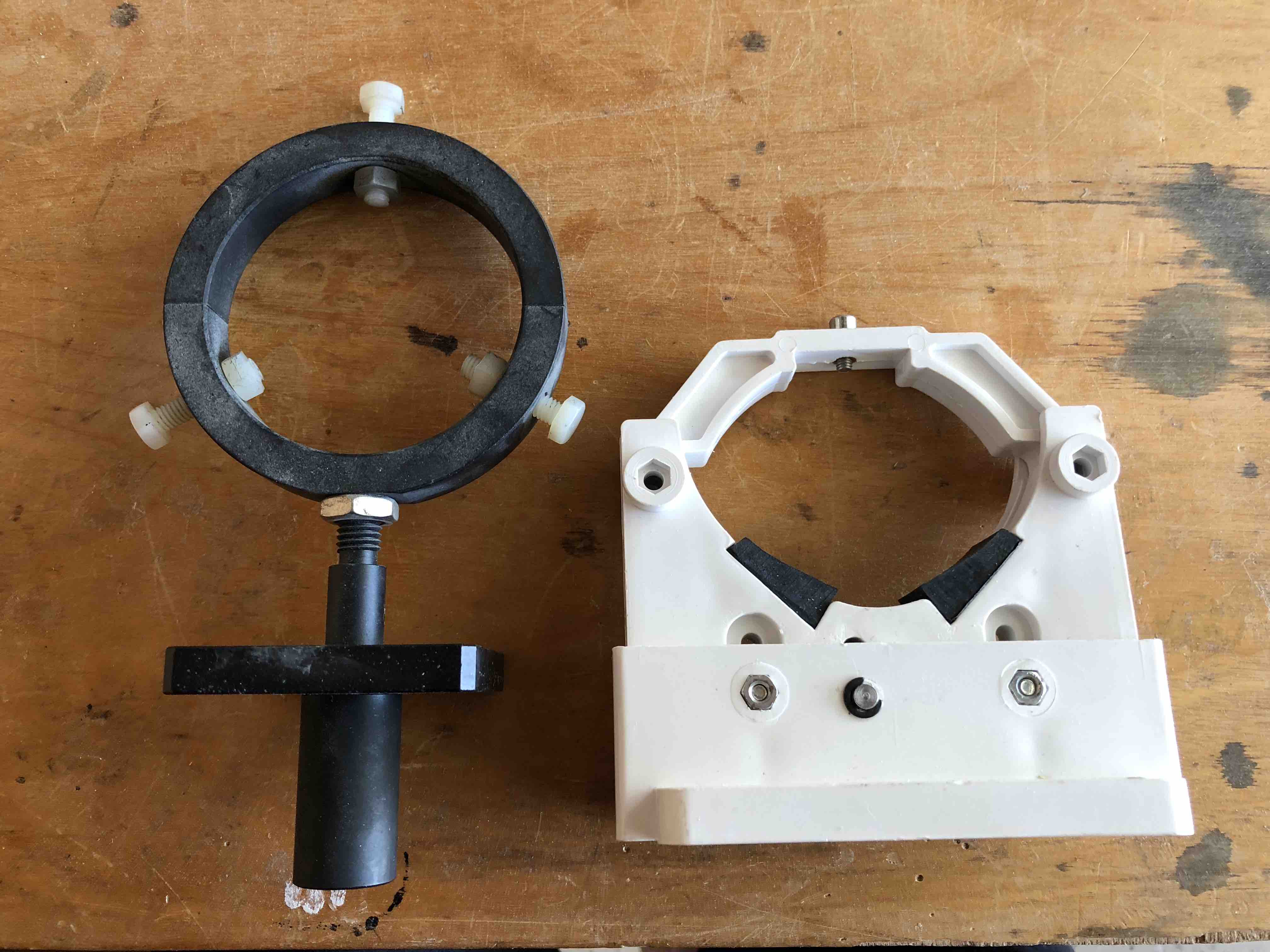
So I printed my own! If you like it, you can find it here and print it, too: https://www.thingiverse.com/thing:2984154


Also important to note: this new tube is almost a foot longer than the original one. So I cut a hole in the side of the enclosure and welded up a box to protrude out and enclose the extra length.


Finally, I have begun the process of wiring. For reference, I am essentially following this wiring diagram exactly: 80W LASER AWC708C SCHEMATIC V5-2
The main controller actually dropped in perfectly. And the motor controllers are mounted to the same heat sinks. In the photo below, the laser power supply and general power supply remain to be mounted.

I greatly enjoyed cutting big holes in the frame to better route wires around, and then printing grommets for them on the spot. Greatly. Enjoyed.


Next big step will be to see if stuff will turn on and move around. Stay tuned!
Leave a Reply
You must be logged in to post a comment.