Almost done!!
Picking up right where we left off last time, here is the laser tube strapped into the adjustable tube holder. The zip ties were a little tricky to thread through given the limited finger clearance, but overall I’m really pleased with how well the brackets fit. The thumb screws under the tube for adjusting vertical alignment were also a bit tricky to get to (I can see why some designs have moved those thumb screws to the top), but overall it wasn’t too bad.

Next step was actually wiring the tube up. The contacts on the tube are actually these wire posts embedded in the glass, so they can’t be soldered or crimped to for risk of cracking the glass. So I ended up just wrapping the high voltage wire around the post and then taking a thin strand of copper wire and tying that on top of everything.

For insulation, I globbed a bunch of clear silicone caulking over my wire wrapping.

The other end of the tube is connected to ground, and the current going through the laser is low, so no insulation needed here.

With the laser tube wired up (and the chiller for keeping the laser cool also tubed up), I was ready to find the max power setting for operating the laser. The home screen on the control panel for the AWC708C lists “Max Power 1, Min Power 1, Max Power 2, Min Power 2”. I don’t really know what the Min Power settings actually do, but Max Power feels pretty self explanatory. The two sets are for 2 different lasers, but I only have the one so I only worry about Max Power 1.
My laser tube came with a paper from the manufacturer that says “this tube can output 61.2 watt power with the current meter reading of 17 mA”. So we (my friend Joshua helped a lot on this) put a multimeter in series on the ground side to measure current and pulsed the laser as we slowly increased the Max Power 1 setting on the controller, each time reading the current measurement. The photo below shows a block of wood providing a target for the laser beam so that it isn’t accidentally hitting something I care about. Also, notice the shop vac hose right above the block of wood. This is to prevent any of the smoke from sticking around and potentially getting onto the mirror or worse, the end of the laser tube. I wasn’t sure if the fume extraction system would be effective in this corner of the enclosure, so better play it safe by adding the shop vac.

Speaking of fume extractors, I offer very little documentation here of how I built mine because I basically followed this awesome Instructable word for word.
At this point, the wiring was almost fully complete. I think the only wires missing in the photo below are the ones of the strip of LED lights I added very last minute to the inside of the enclosure.

The photo below shows the fairly brute force method that I went about squaring the axes. Joshua lent me this sweet square with a pretty wide base. I clamped it to the rail on the right. You can see there is a variety of extra extrusions also clamped in place to provide parallel but offset surfaces for the square to touch. The X axis rail is driven by a belt on each side. Each belt is attached to a pulley that is on either end of an axle at the very back of the machine. This axle is then driven by a stepper motor. For squaring, I loosened just one of these pulleys so that I could adjust the angle of the X axis rail, and then tightened it down when it was square.

Ok, so the laser turns on, the axes move. It is time for laser beam
alignment! A quick search for ‘laser cutter mirror alignment’ yields tons of resources, so I just offer a quick summary here: The laser beam needs to travel vertically through the center of the lens in order to cut through the material vertically, and to do this in all parts of the workspace, the laser beam needs to be parallel to the X and Y axes. In practice, this involves clipping a little U-shaped sheet metal piece (I used aluminum flashing) with masking tape to the mirror downstream of the one you are aligning, then pulsing the laser twice – once close and once far from the mirror being aligned – and adjusting until both pulses hit the same spot.
However, remember how the beam needs to go through the center of the lens, which is the most downstream from the laser tube? This meant that I would square all the axes, find that the beam was a little off center going through the lens, then I would make some adjustments upstream, which would mean more downstream alignment, and so on. Lots of tape was harmed in the process.

Here is a cartoon illustrating the importance of hitting the center of the lens. Being off-center results in the cut being angled.

One way to double check that the beam is perpendicular is to pulse it through a material of some thickness. I used 1/4″ acrylic.

The pulsed holes can be viewed from the edge to see how square it is to the material. I checked along two edges to make sure the beam was square to both axes.

Next step is tuning the “um/pulse” (stepper motor pulse) so that parts come out the right size. I started by just moving the laser head and pulsing two points. But I think this is the easiest: make a part with two holes and just measure the center to center distance. This takes out any variation you get with kerf.

Finally, I am able to cut some stuff!! Below is a piece of 1/8″ delrin. I can see that I have quite a bit of fiddling to find the right speeds and power settings for various materials, but I am pretty excited to start making some stuff with it.

Here is the beginning of finding the right settings for certain materials. I think the right way is to just make a file that has a grid of circles spanning cut speeds and powers, then just seeing which circles fall through after being cut. I might do something similar for engraving settings, too.

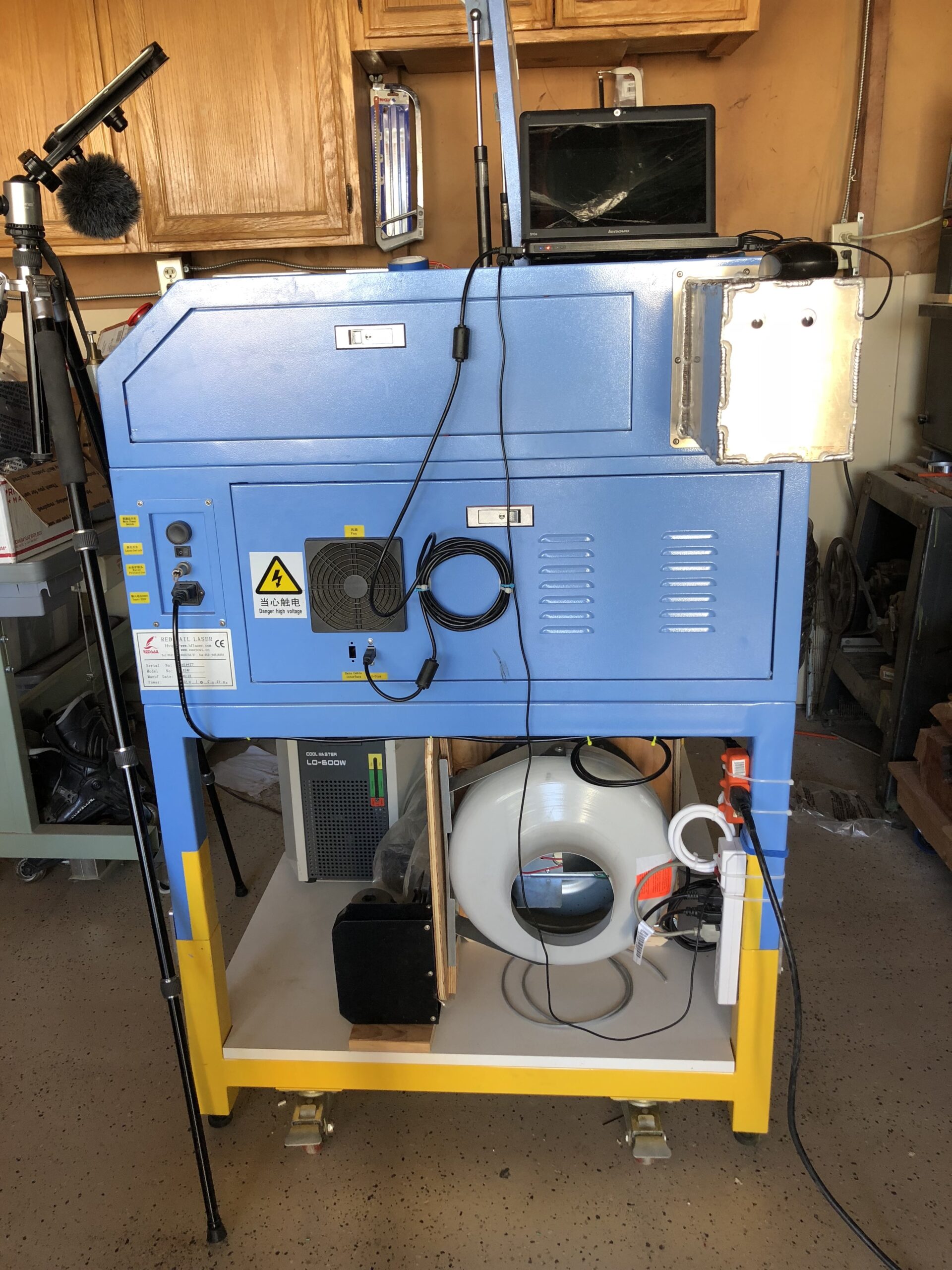
Here are some photos of the final setup. I have an old netbook connected to the laser cutter via USB. There is a 3 plug splitter (orange) that powers the netbook, controller, and power strip. The power strip then powers the fume extractor, air compressor, and chiller. I’ve separated them so that I can do all my setup with the loud stuff on the power strip off and just turn them all on right before I cut. This also means that at the moment, I could potentially turn on the laser without having the chiller on. So I’ll probably end up wiring the chiller to the enable pin on the controller to protect against this.
You can also see that for now the fume extractor exhausts into the work space. With the activated carbon filter, I actually don’t smell anything in the exhaust so far, but in the future, I’ll probably duct this to exhaust outside.

This shows the fume extractor ducting to the laser enclosure.

From this angle you can see the water-filled tubes that run between the chiller and the laser tube, as well as the air tube (black) that runs between the air compressor and the nozzle on the cutting head. I found it quite difficult to source air compressors specifically meant for laser cutters. So I ended up getting a 102W air pump for an aquarium or hydroponic setup, and its seems to work great.

Whew, what a build!
Huge thanks again to Joshua, who helped a ton throughout this build, especially in the last stretch covered in this video.
Leave a Reply
You must be logged in to post a comment.