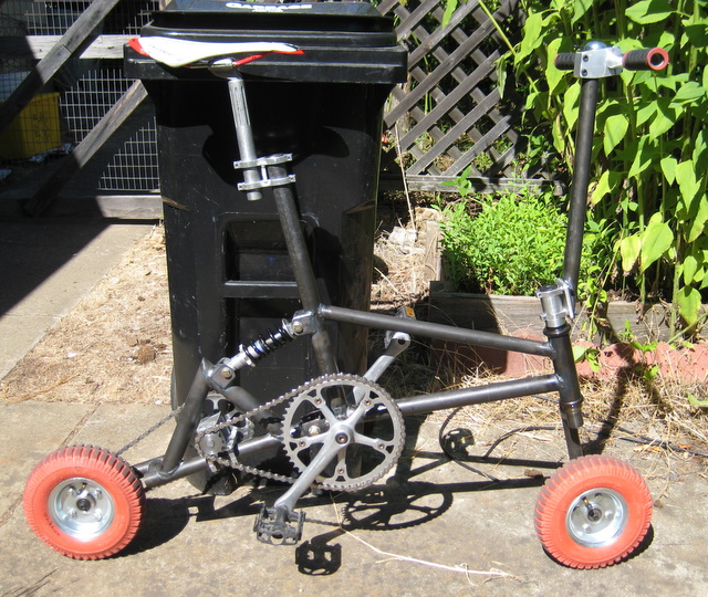
I guess I always say it is going to be the last for a while, so we’ll see how long it lasts this time… Anyhow, this time it coincides a bit with the end of an era: I have graduated and re-situated myself on the west coast once again. For most of July I was traveling, and the last two weeks I was packing, hence the lapse in posting. But there was time for one last build, of course. Introducing: Blitzen the Bike.


So…what’s special about this one? Well, its a custom welded steel chromoly frame with suspension, the wheel axles are cantilevered, and gearing is done so that, despite the small wheels, you’ll go the same distance as my normal sized bike with every crank rotation. It came out a bit back-heavy due to all the extra gearing, the front end is a bit unstable due to the angle of the extended stem tube, and of course there is the increased risk of tipping forward because of the much smaller wheels. So this bike is definitely not about to wow anyone with performance, but it makes a fun ride.
I started with some 8″ pneumatic wheels from Harbor Freight. Originally, I was looking for the smallest pneumatic wheels I could find, but these turned out to be a great deal cheaper than any other option. And they turned out to be a good size for what I ended up doing. However, their biggest drawback is the stock bearings they come with, so the first thing to do is a bearing replacement.

I was able to remove the stock bearings and just turn some adapters for some standard 0.5 inch ID bearings I had lying around.
Next, I started working on the front fork, which would use 1.125″ threadless headset. This means that although the headset tube is 1.125″ in diameter, the diameter that the lower bearing race presses on to is actually more like 1.150″. This was tricky because it was too thin for me to reliably machine a spacer, and I needed something accurate and strong enough to support the bearing. I ended up using a short section of 1/8″ wall tubing 1.125″ ID and welding it all the way around the head tube on both ends. This effectively increase the diameter of the tube so I could machine a nice bearing race step.

The wheel axles on this bike are only supported on one side. This is usually not the optimal setup because it’s usually much harder to provide enough support in this configuration. However, in this case the wheels lend quite well to cantilever support because the hub is already skewed so far to one side. I think they are designed for hand trucks, whose wheels are often supported on only one side anyway. I just drilled a 0.5″ hole at the end of the fork tube and welded a 0.5″ solid rod into it. The end of the rod is tapped for a screw that will hold the wheel on the axle. Time will tell if this is actually strong enough.

Fish mouthing a piece of tube to connect the fork tube and head tube was a bit hand wavy. Sometimes, people calculate the angles exactly, and then use the appropriately sized hole saw to miter the ends. Instead, I used a cold saw and bandsaw (you could also use an abrasive chop saw) to make straight cuts that approximate a perfect fish mouth cut. The idea to do this came from this website, which also has suggested angles depending on the diameter of tubing you are joining.
I mostly used diameter combinations that were not on this chart, so I just extrapolated between their suggested angles. I also found that for angled joints, you can just offset their suggested cut angles by the desired tubing angle. For example, let’s say you are joining 1″ to 1″ at an angle 15deg from perpendicular. The perpendicular suggested cut is 20deg, so instead, cut your at 5deg and 35deg. For a joint that is 30deg angle from perpendicular, cut the tube at 50deg and 10deg the other way (it will come out not really like a “fish mouth” anymore, since both cuts will slope the same way).


The next day I started working on the rest of the frame. I had a CAD of the frame which I transferred to scale to a piece of cardboard with a ruler and Sharpie. This served as a general guideline for the correct angles. Again, all the tubing was standard fractional English sizes, so it was easy to use spacers to ensure all the tubing was properly aligned.


Next, I started working on pivot mounts for the shock. I used 1/8″ wall tubing. I didn’t want to have to bridge a huge gap when welding, and I luckily happened upon a hole saw of the right size, so I used that.

Unfortunately, the hole saw did not last long, and I was only able to finish one mount before the saw cracked. Sadface. Step drill to the rescue!

It was actually a bit messy, and I had to grind some stuff with a Dremel anyway, but still much faster than having to grind everything.
Next I turned to the swing arm pivot. The back of the bike will pivot off this when the shock compresses.


Welding the front part of the pivot to the frame proved tricky because there were huge gaps to bridge. In the picture below you can see that I am welding the pivot directly to the bottom bracket. The bottom bracket was actually cut out of a scrapped bike frame (so that I don’t have to tap my own bottom bracket), so it still has all the holes where the old tubing used to be. The worst part is that the old frame was brazed together, so in fact there are still pockets of the brazing material in the steel, which made welding around this part a real pain. In retrospect, I wish I had searched for a clean bottom bracket, but there wasn’t really any time for that I guess. Anyhow, to bridge the gap, I didn’t think I could do it just with filler rod, so I welded in little pieces of scrap.


Hopefully this is all strong enough…
Next I started working on the rear swing arm. There was a nice straight mitered joint to weld, which came out nicely.


I’m not sure that stem clamp is even the name of a real part, but hopefully it becomes clear what I mean. There are lots of extra sprockets in case I mess up.

Lots of people asked me why I didn’t just have the seat post go into the tube of the frame, instead of using this clamp. I like using this better for several reasons: I can bore the clamp diameter out exactly, instead of making a spacer for the frame tube, and I can independently choose the angle of the seat post, instead of relying on the frame shape, which I did not think about too thoroughly.
Let’s make some sprockets. I went to a bike shop and bought a used crankset with a 52 teeth chainring. This will drive a 12 tooth connected to a 32 tooth. And the 32 tooth drives a 16 tooth that is fixed to the rear wheel (yup, its a fixie).


The bearing block for the assembly above was also made of waterjet piece welded together. I like this kind of assembly technique because I can easily start with a part that has most of the material removed. Its also a lot easier to find room for welds than for fasteners. Also, in the end, there are fewer parts. Most of this never needs to come apart anyway.

The stem stuff assembles the same as any other threadless setup. I hammered (carefully) a starnut into the fork. Be sure to check it frequently while hammering to make sure it is still going in straight. You do have to hammer pretty hard, too.

And shown below is where that stem clamp came into play. The actual handle bars are connected to the extension tube that goes off into the upper right corner.

Finally, my bike needed a stem. Yea, yea, I could have bought this. But machining it meant I could have it sooner. I checked some bike stores, but no one had anything this short anyway. The tubes are practically tangent, but it works out well for this bike’s geometry.

In the end, I was even able to pack this bike into a box that fit the 62″ dimension limit of most airlines, so I didn’t even have to pay a special bike shipping fee!
Okay, that’s all. Thanks for tuning into extended-blog-post-edition-cuz-I-couldn’t-get-my-act-together-to-blog-earlier.
Leave a Reply
You must be logged in to post a comment.